Introduction
In this post I drive an RC servo motor using the PWM output of a timer on the CH32V003 microcontroller.
Environment
- RC servo motor: MG90D (digital servo)
- Microcontroller: CH32V003F4P6 (SSOP-20)
- IDE: MounRiver Studio Ⅱ (the official VSCode-based development environment)
- SDK: official SDK (bundled with MRS2)
Wiring
Connect the servo signal wire to the PD2 pin of the microcontroller (TIM1 channel 1 output).
Servo wire connections:
- Yellow (signal) → PD2 (pin 19)
- Red (power) → 5 V
- Brown (GND) → GND

Timer Configuration
The signal needed to control the servo is generated with the PWM output of Timer 1 (TIM1).
- Count frequency: 1 MHz
- So that the pulse width can be set in microseconds (us)
- Generated by dividing the MCU clock (48 MHz) by 48 with the prescaler (the actual division ratio is computed dynamically from the global variable
SystemCoreClock, which holds the MCU operating frequency)
- Period: 20 ms (20,000 counts)
- Sets the PWM signal repetition rate to 50 Hz
Program
First, create a project in MounRiver Studio Ⅱ. (How to create and configure the project is covered in the previous article.)
To make the servo control functions easy to reuse, I put them in separate files rather than in main.c. Add the following two files (servo.h, servo.c) to the User folder.
#ifndef __SERVO_H
#define __SERVO_H

#include "ch32v00x_conf.h"

#ifdef __cplusplus
 extern "C" {
#endif

void Servo_Init(void);
void Servo_SetPulse(uint16_t us);

#ifdef __cplusplus
}
#endif

#endif /* __SERVO_H */
#include "servo.h"

/* Servo initialization */
void Servo_Init(void) {
    /* Supply clock to GPIO and TIM1 */
    RCC_APB2PeriphClockCmd(RCC_APB2Periph_GPIOD | RCC_APB2Periph_TIM1, ENABLE);

    /* Initialize PD2 in AF (Alternate Function = output driven by a peripheral) mode */
    GPIO_InitTypeDef GPIO_InitStructure = {0};
    GPIO_StructInit(&GPIO_InitStructure);
    GPIO_InitStructure.GPIO_Pin = GPIO_Pin_2;
    GPIO_InitStructure.GPIO_Speed = GPIO_Speed_30MHz;
    GPIO_InitStructure.GPIO_Mode = GPIO_Mode_AF_PP;
    GPIO_Init(GPIOD, &GPIO_InitStructure);

    /* TIM1 configuration */
    TIM_TimeBaseInitTypeDef TIM_TimeBaseInitStruct = {0};
    TIM_TimeBaseStructInit(&TIM_TimeBaseInitStruct);
    TIM_TimeBaseInitStruct.TIM_ClockDivision = TIM_CKD_DIV1;
    TIM_TimeBaseInitStruct.TIM_CounterMode = TIM_CounterMode_Up;
    TIM_TimeBaseInitStruct.TIM_Prescaler = SystemCoreClock / 1000000 - 1; /* Division ratio (note the -1) */
    TIM_TimeBaseInitStruct.TIM_Period = 20000; /* Period */
    TIM_TimeBaseInit(TIM1, &TIM_TimeBaseInitStruct);

    /* TIM1 output channel 1 configuration */
    TIM_OCInitTypeDef TIM_OCInitStruct;
    TIM_OCStructInit(&TIM_OCInitStruct);
    TIM_OCInitStruct.TIM_OCMode = TIM_OCMode_PWM1; /* Output mode */
    TIM_OCInitStruct.TIM_OutputState = TIM_OutputState_Enable; /* Enable output */
    TIM_OCInitStruct.TIM_Pulse = 0; /* Initial pulse width */
    TIM_OC1Init(TIM1, &TIM_OCInitStruct);

    /* Enable TIM1 */
    TIM_CtrlPWMOutputs(TIM1, ENABLE);
    TIM_OC1PreloadConfig(TIM1, TIM_OCPreload_Enable);
    TIM_ARRPreloadConfig(TIM1, ENABLE);
    TIM_Cmd(TIM1, ENABLE);
}

/* Set the servo signal pulse width (unit: us) */
void Servo_SetPulse(uint16_t us) {
    TIM_SetCompare1(TIM1, us);
}
Testing
Write a test program.
#include "debug.h"
#include "servo.h"

int main(void)
{
    NVIC_PriorityGroupConfig(NVIC_PriorityGroup_1);
    SystemCoreClockUpdate();
    Delay_Init();
#if (SDI_PRINT == SDI_PR_OPEN)
    SDI_Printf_Enable();
#else
    USART_Printf_Init(115200);
#endif

    Servo_Init();

    Servo_SetPulse(1500); /* Center */
    Delay_Ms(1000);
    Servo_SetPulse(1000); /* Maximum in the reverse direction (about -45 degrees) */
    Delay_Ms(1000);
    Servo_SetPulse(2000); /* Maximum in the forward direction (about +45 degrees) */
    Delay_Ms(1000);
    Servo_SetPulse(1500); /* Center */
    Delay_Ms(2000);

    while (1) {
        for (uint16_t i = 1000; i <= 2000; i+=100) {
            Servo_SetPulse(i);
            printf("Pulse: %d\n", i);
            // Delay_Ms(500);
        }
    }
}
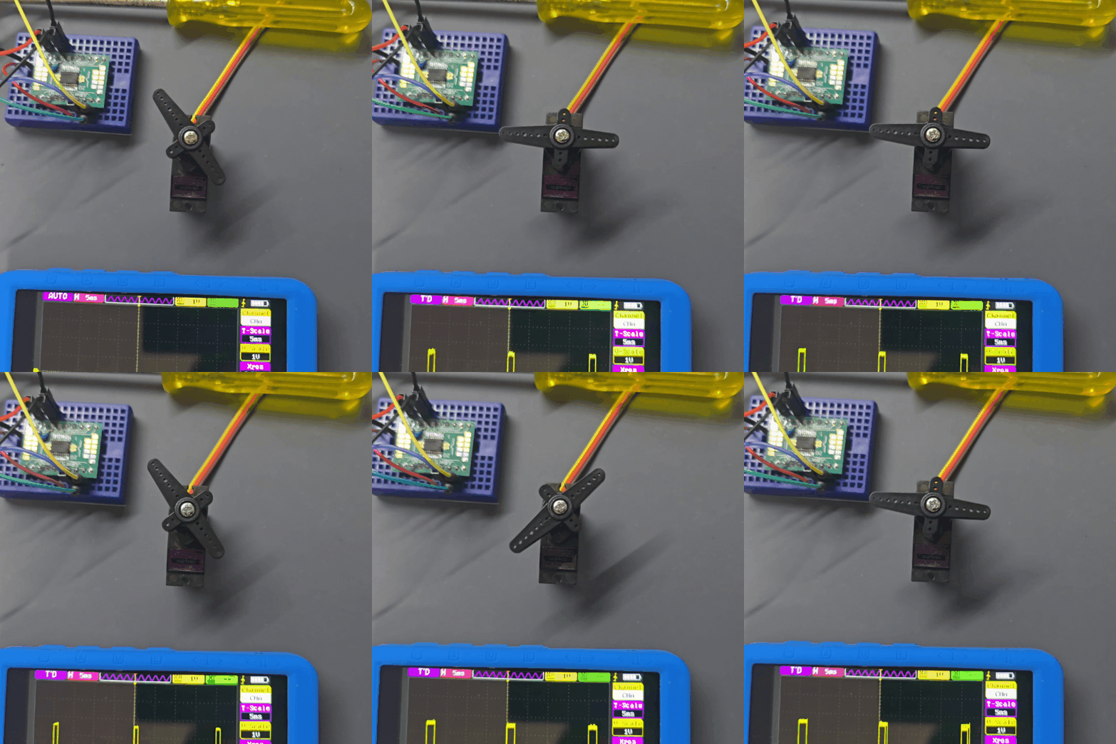
The program first moves the servo center → -45 degrees → +45 degrees → center, then sweeps in one direction while printing the current position with printf.
If you are not using the debug feature, replace printf with the Delay_Ms function.
The following GIF shows it running (first half only).
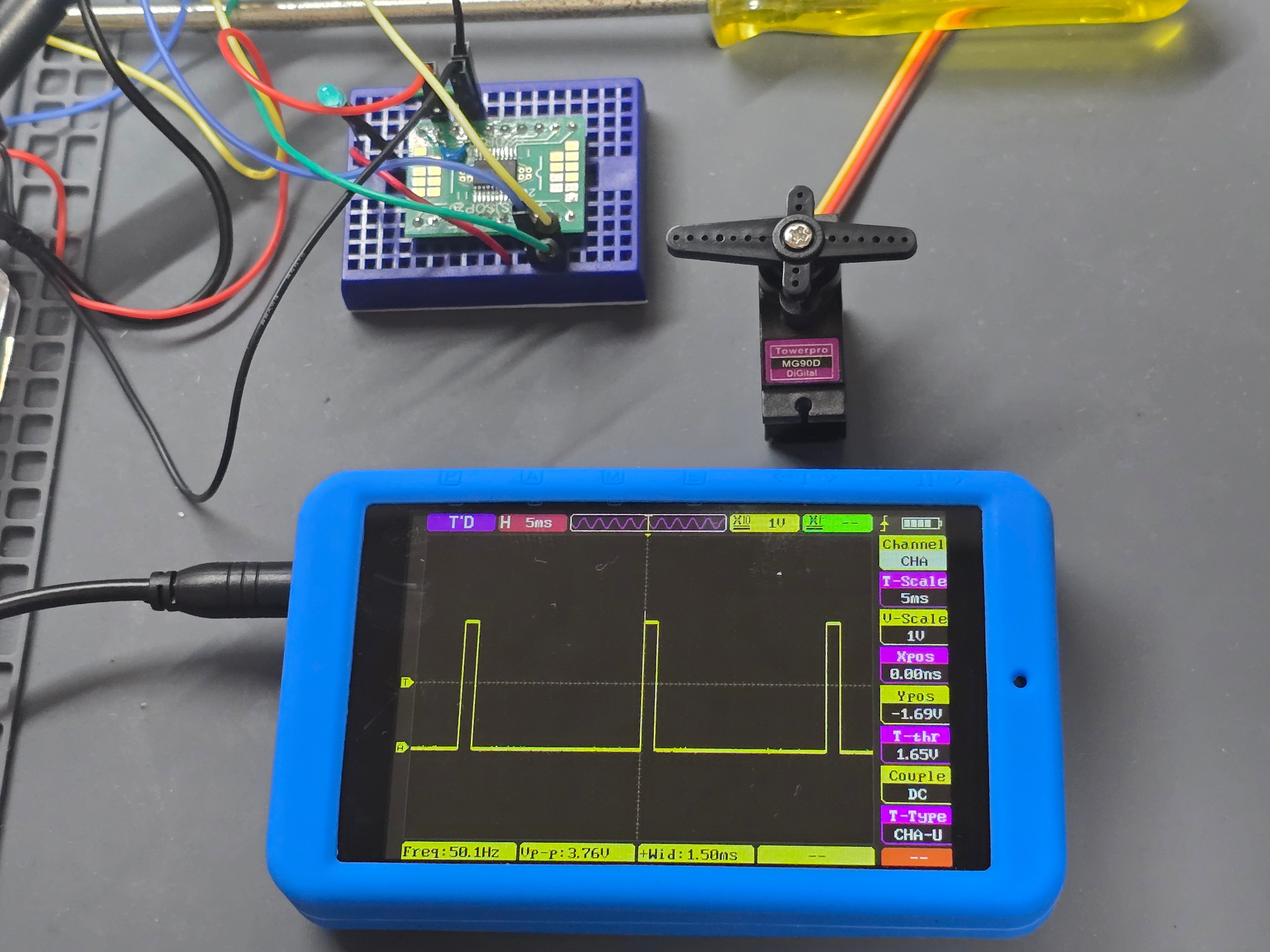
Below is the PWM output signal fed into an oscilloscope. The readout at the bottom of the scope shows a 1.5 ms pulse being output at a clean 50 Hz (20 ms) interval. The scope I use is the Alientek DS100 mini digital oscilloscope, which makes it easy to debug MCU output signals like this one.
.DQ0twJun.jpg)
Summary
I generated a PWM output on the CH32V003 microcontroller with the official SDK and used it to control an RC servo motor.
I plan to try out the other peripherals as well.
References
CH32V003EVT.ZIP (WCH official evaluation board package)
It contains the development board documentation plus a wide range of sample code organized by feature, so if you are unsure how to use the official SDK, this is the quickest place to look. The PWM output code was based on EVT/EXAM/TIM/PWM_Output/User/main.c.