_(カスタム).Ds8SoApd.jpg)
Introduction
In this article I set up a development environment for the CH32V003, a low-cost microcontroller that Akizuki Denshi sells for 60 yen, and write a program for it.
I use the recently updated, VSCode-based development environment (MounRiver Studio Ⅱ), build an actual test circuit, and try out debugging and LED blinking.
Required parts
- Microcontroller: CH32V003F4P6 (AliExpress)
- Debugger: WCH-LinkE (AliExpress)
- Adapter board: SSOP20 (0.65 mm) to DIP adapter board (Akizuki Denshi)
- Other parts
- 0.1 μF multilayer ceramic capacitor (for decoupling)
- Jumper wires
- Breadboard
- LED and current-limiting resistor
Overview of the CH32V003 microcontroller
CH32V is a family of RISC-V microcontrollers from Nanjing Qinheng Microelectronics (WCH) in China. Within that family, the CH32V003 is the inexpensive entry-level model.
Features of the CH32V003 series
- Core: QingKe 32-bit RISC-V2A
- Operating frequency: up to 48 MHz (an internal clock can be used)
- SRAM: 2 KB
- Flash: 16 KB
- Timers: 2
- 16-bit advanced timer x1
- 16-bit general-purpose timer x1
- Main peripherals: ADC, I2C, SPI, UART
The feature set is not exactly rich, but the basic peripherals are there, and with a 32-bit core running at 48 MHz it performs well compared with 8-bit microcontrollers, so it should be useful for many things.
There are also higher-end series such as the CH32V203, which add peripherals like USB and CAN.
Where to buy
Akizuki Denshi sells the chips individually, and buying in bulk from AliExpress is even cheaper.
- Akizuki Denshi: individual chips are also available at the store in Akihabara, Japan
- CH32V003J4M6: 8-pin (SOP8), 40 yen each (Akizuki Denshi product page)
- CH32V003F4P6: 20-pin (SSOP20), 50 yen each (Akizuki Denshi product page)
- AliExpress: there is an official WCH store (WCH Official Store), so buying from there is probably the safest option
- Bare chips (WCH official store): sold in lots of 50
- A starter-kit-like bundle (not from WCH): a set with a CH32V003F4P6 evaluation board, a WCH-LinkE programmer and 5 CH32V003F4P6 chips
Development environments
Because the generic GCC cross-compiler for RISC-V can be used, there are several ways to develop besides the official environment.
- MounRiver Studio (MRS): the official IDE
- VSCode + PlatformIO: https://github.com/Community-PIO-CH32V/platform-ch32v
- Arduino IDE: https://github.com/openwch/arduino_core_ch32
- ch32v003fun: a community-based development environment, usable from PlatformIO or the CLI (Makefile-based)
- Rust: https://github.com/ch32-rs/ch32-rs
For this article I use the official environment, MounRiver Studio.
MounRiver Studio Ⅱ (MRS2) was released recently. The original MRS was Eclipse-based and Windows-only, but MRS2 has been rebuilt on VSCode and now supports Windows, macOS and Linux.
I develop with this new MounRiver Studio 2 here and also take a look at how it feels to use.
WCH-LinkE (programmer and debugger)
.CVwFuvTi.jpg)
.C48Zo4Ks.jpg)
This is used to program the microcontroller. The WCH-LinkE also works as a debugger, so you can use the IDE's debug features to inspect variables and register values directly while the program runs. It also provides a UART and a 3.3 V/5 V power supply, so this one device is enough to start CH32V development.
It connects to the microcontroller over the 1-Wire Serial Debug Interface (SDI), which needs only a single wire to the microcontroller's SWIO pin. This is simpler than the SWD interface on ARM microcontrollers (two wires: SWDIO/SWCLK).
Setting up MounRiver Studio Ⅱ
Installation
- Go to the official MounRiver site
(Whether because the server is weak or because access is throttled, you may be held at the waiting screen shown below when opening the site. If that happens, wait a while and then reload.).C_V-nkCW.png) Loading screen on the MounRiver site
Loading screen on the MounRiver site - Download the MounRiver Studio Ⅱ (MRS2) installer
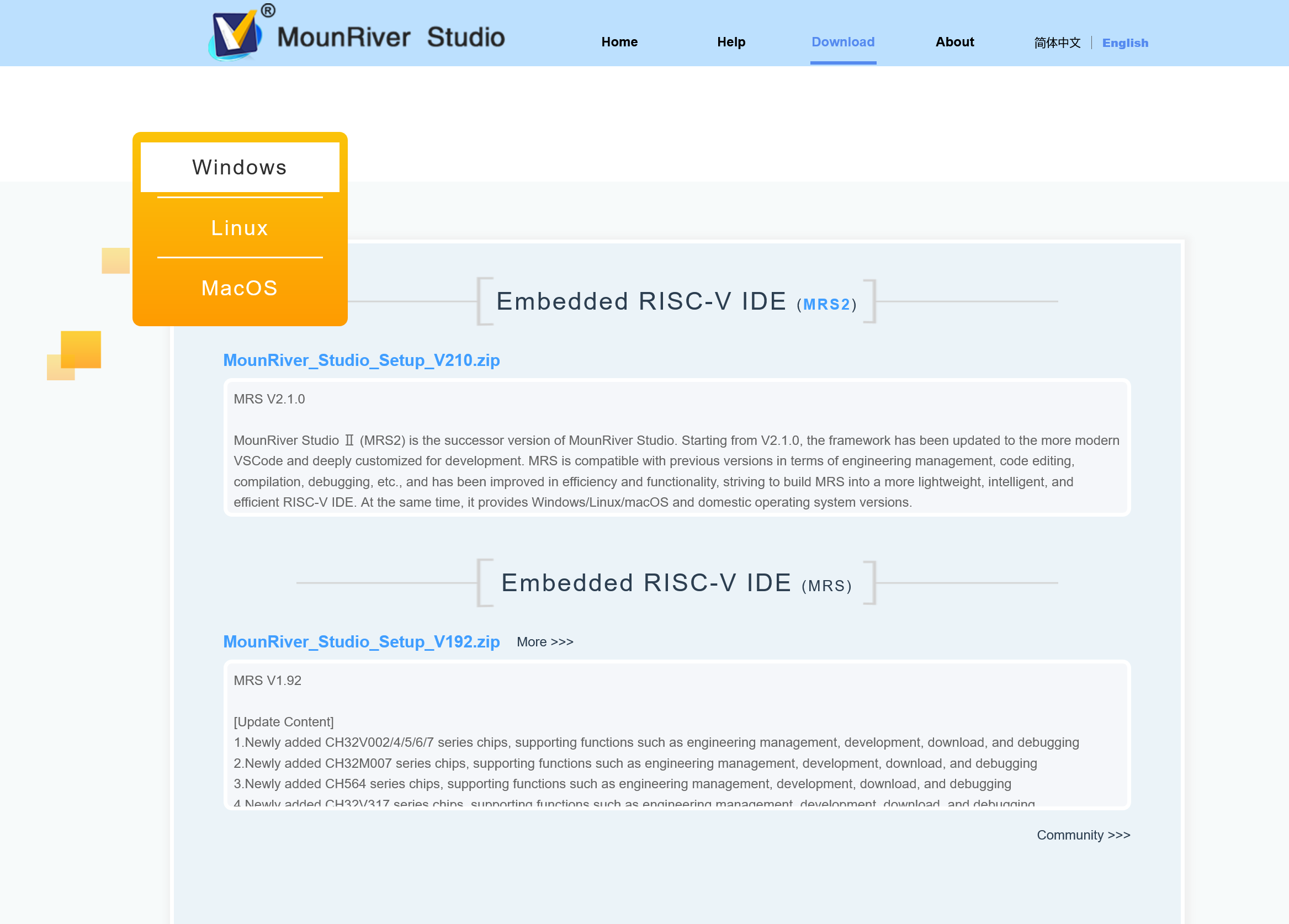 MounRiver Studio download page
 - Run the installer and follow the instructions
.C_V-nkCW.png)

Launching and looking at the new VSCode-based MRS2
Launch MounRiver Studio Ⅱ from the desktop or Start menu shortcut. Perhaps because the base changed from Eclipse to VSCode, it starts quickly, without the long splash screen that Eclipse-based IDEs tend to have.
Below is the initial screen after launch. MRS2 is VSCode with customizations added, and compared with plain VSCode it differs in things like the extra row of tool buttons at the top.

The layout-switching buttons in the top right look like they bring over the Perspective concept from Eclipse.

Creating a new project
- Click "Create MounRiver Project" on the initial screen, or File→New→MounRiver Project in the menu, to open the project creation screen
- Configure the project creation screen as follows
- Microcontroller selection: CH32V003F4P6
- Location: where to save the project
- Project Name: any project name
- Template Type: NoneOS (default)
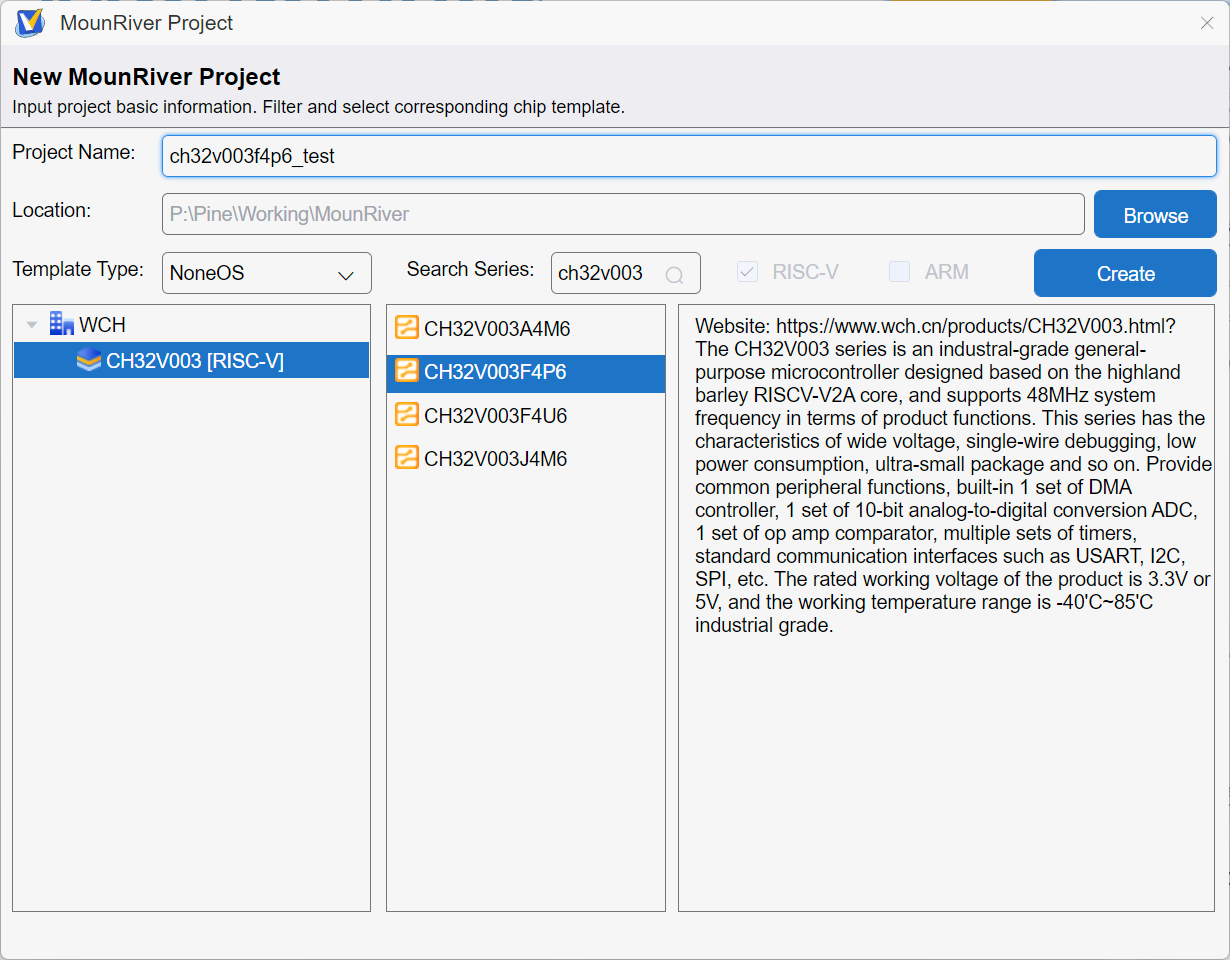
- Click Create to create the project
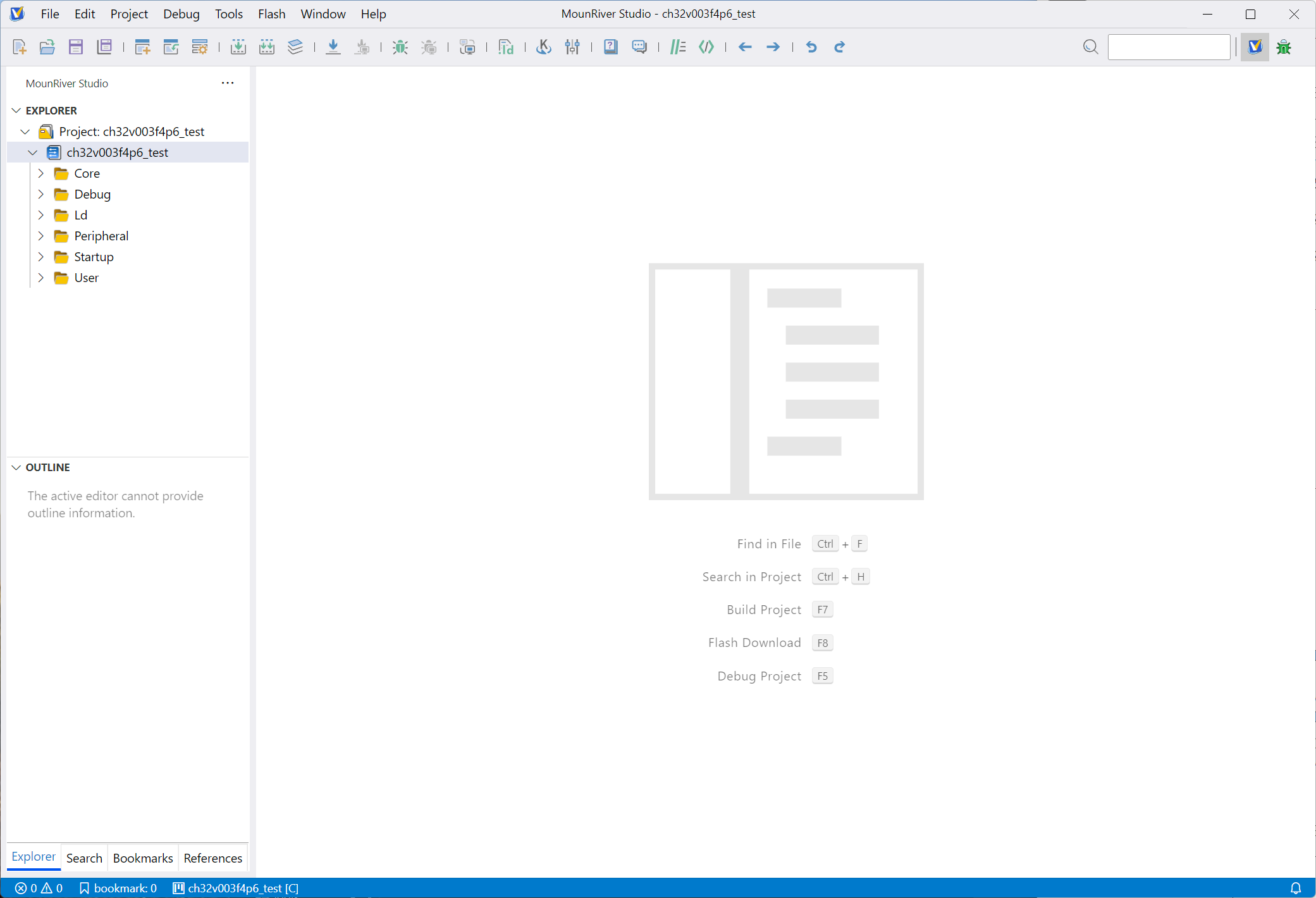


Initial project settings
Clock settings
Open User/system_ch32v00x.c and change the clock configuration define to SYSCLK_FREQ_48MHZ_HSI (internal oscillator HSI, system frequency 48 MHz) as shown below.
#define SYSCLK_FREQ_48MHZ_HSI   48000000 // uncomment this line (remove the leading //)
// #define SYSCLK_FREQ_48MHz_HSE   48000000 // comment this line out (add // at the start)
Building the test circuit
For the microcontroller I use the CH32V003F4P6, which Akizuki Denshi sells for 50 yen.
This microcontroller comes in a surface-mount package (SSOP20), so I solder it to a DIP adapter board sold by Akizuki Denshi and fit pin headers so it can be plugged into a breadboard.
As a decoupling capacitor, I also add a 0.1 μF multilayer ceramic capacitor directly on the adapter board between the VDD and VSS power pins.

The schematic for the breadboard circuit is as follows.

Old schematic (wrong pin connection)

The microcontroller pins and their connections are listed in the table below.
| Pin number | Function | Connected to | Purpose |
|---|---|---|---|
| 7 | VSS | WCH-LinkE: GND pin | GND |
| 9 | VDD | WCH-LinkE: 3.3V pin | Power supply |
| 11 | PC1 (GPIO pin) | LED (green) + resistor | LED blinking |
| 18 | SWIO | WCH-LinkE: SWDIO pin | Debug communication |
I build the circuit on a breadboard using the microcontroller on the DIP adapter board and connect it to the WCH-LinkE. The yellow LED at the bottom of the breadboard is for confirming the power supply, and the green LED at the top is for confirming operation (LED blinking).
_(1).N_Vo45rA.jpg)
Checking operation
Checking the initial program
Open User/main.c and you will find a sample program in the main function. First I run this program as it is. It is a sample program that uses the USART, but I ignore that for now and only check whether the printf output can be shown through the debugger.

Building and flashing the program
- (First time only) Switch the WCH-LinkE from ARM development mode to RISC-V mode
In the project properties, choose Download→Download Settings, set Debugger Target Mode to RISC-V and click the Apply button.
At some point in the process you will probably be asked to upgrade the WCH-LinkE firmware; do so when prompted.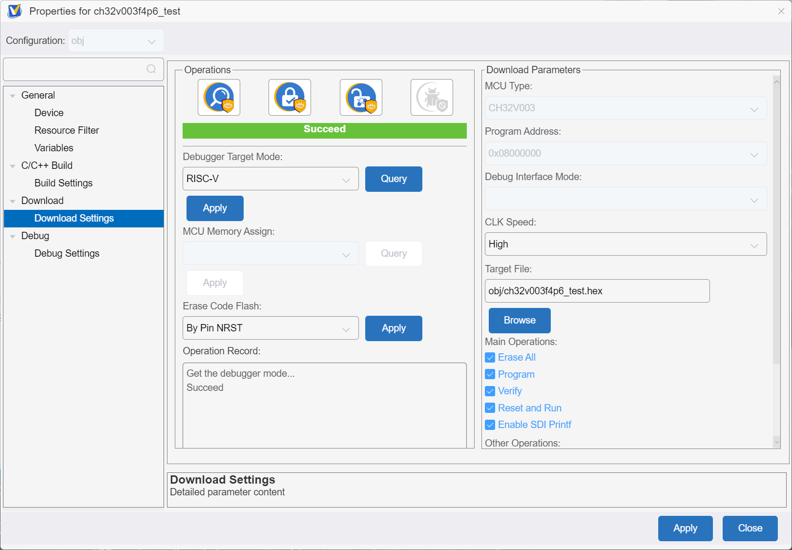
- Click Build Project among the tool icons at the top of the screen to build the program
- Click Download among the tool icons to flash the program to the microcontroller⚠️Always build the program before pressing the Download button. It does not build automatically, so you would otherwise flash an old program.
- At this point the flashed program should be running, but since nothing is connected to the USART you cannot tell whether it is working.

Debug settings (SDI printf)
As a convenient feature for the debugging work that follows, I enable SDI printf, which lets the program print text directly to the debug console through the debugger.
(I could not find documentation, so I am not sure this is the correct procedure)
- Open Project→Property in the menu
- Open C/C++ Build→Build Settings→Tool Settings→GNU RISC-V Cross C Compiler→Preprocessor and add
SDI_PRINT=SDI_PR_OPENto Defined symbols
(this does not seem to be required)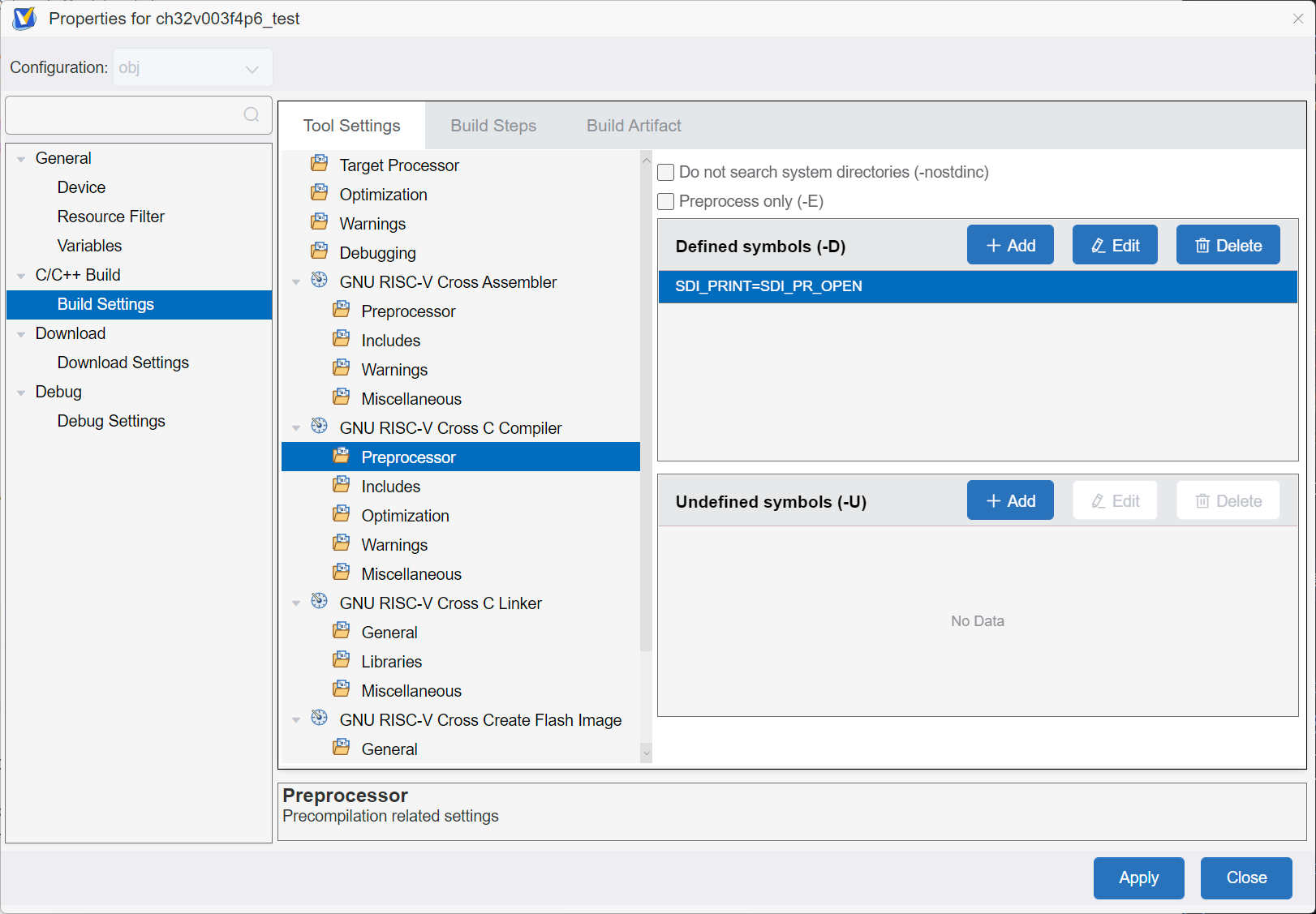
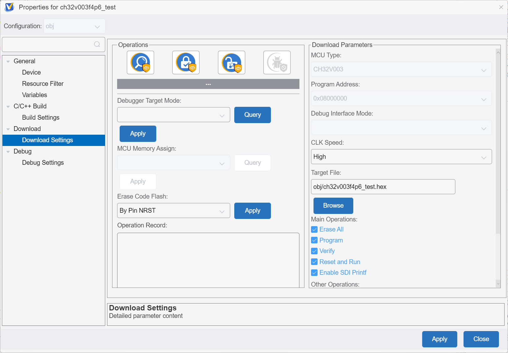
- Open Download→Download Settings and check Enable SDI Printf (this also does not seem to be strictly required)
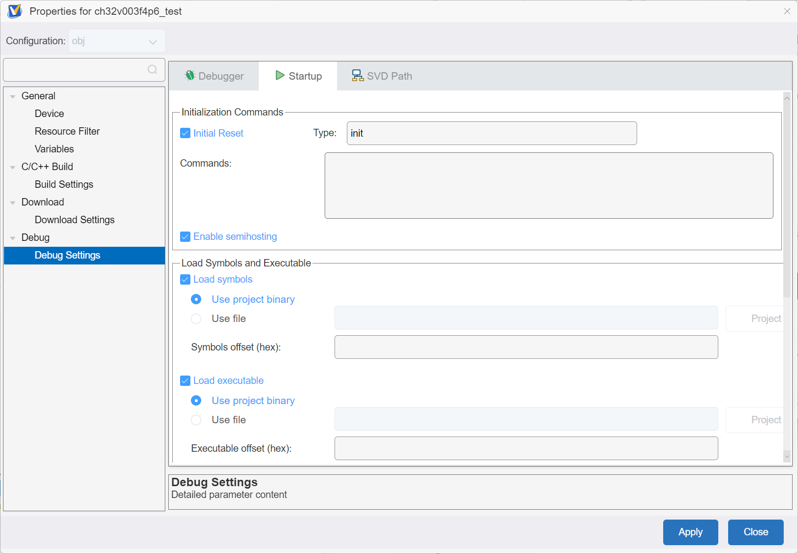
- Open the Debug→Debug Settings→Startup tab and check Enable Semihosting (this is the only required step)
- Save the settings with the Apply button
Note that clicking the Close button discards the settings without a confirmation dialog
- Rebuild with the Rebuild Project button
Note that a plain build does not pick up the changes


Checking the debug output
I debug in real time using the debugger function of the WCH-LinkE.
- Click Start Debug among the tool icons to start debugging
With the default settings, the program pauses at an early stage of the startup assembly.
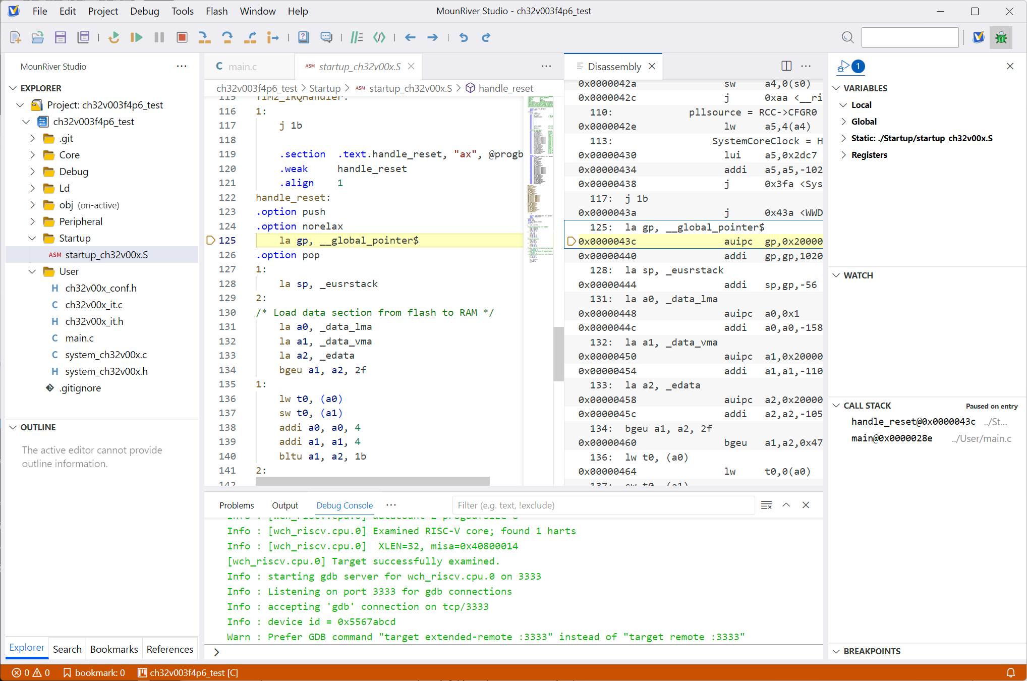
- Press the Continue button and the program runs. If the settings are right, the system clock and chip ID should be printed in the Debug Console at the bottom, as in the figure.
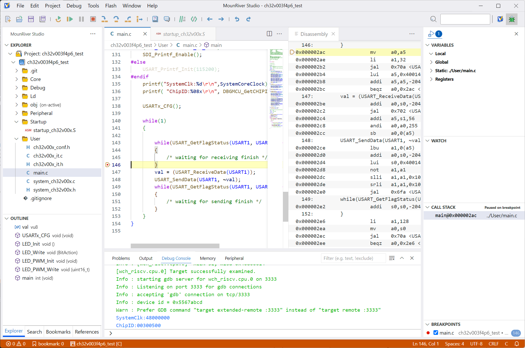 Checking the printf output


Blinking an LED
As the classic first microcontroller program, I blink an LED. In this circuit the LED is connected to the microcontroller's PC1 pin.
The GPIO needs to be initialized, so I add the following function above the main function in main.c.
void LED_Init() {
    // Supply the clock to GPIOC
    RCC_APB2PeriphClockCmd(RCC_APB2Periph_GPIOC, ENABLE);

    // Prepare the GPIO configuration struct
    GPIO_InitTypeDef GPIO_InitStructure = {0};
    GPIO_InitStructure.GPIO_Pin = GPIO_Pin_1; // use PC1
    GPIO_InitStructure.GPIO_Speed = GPIO_Speed_30MHz; // output speed
    GPIO_InitStructure.GPIO_Mode = GPIO_Mode_Out_PP; // push-pull output mode
    // Apply the configuration to the GPIO
    GPIO_Init(GPIOC, &GPIO_InitStructure);
}
I also write a function that turns the LED on and off.
void LED_Write(BitAction BitVal) {
    GPIO_WriteBit(GPIOC, GPIO_Pin_1, BitVal);
}
Using these, I rewrite the main function into the LED blink program.
int main(void)
{
    NVIC_PriorityGroupConfig(NVIC_PriorityGroup_1);
    SystemCoreClockUpdate();
    Delay_Init();

    // Debug output (SDI Printf)
    // Comment out this whole block when not using the debugger
#if (SDI_PRINT == SDI_PR_OPEN)
    SDI_Printf_Enable();
#else
    USART_Printf_Init(115200);
#endif
    printf("SystemClk:%d\r\n",SystemCoreClock);
    printf( "ChipID:%08x\r\n", DBGMCU_GetCHIPID() );

    // GPIO initialization
    LED_Init();

    // Main loop
    while(1)
    {
        LED_Write(Bit_SET); // LED on
        Delay_Ms(500); // wait 500 ms
        LED_Write(Bit_RESET); // LED off
        Delay_Ms(500); // wait 500 ms
    }
}
When I debug and run it, the connected LED blinks every 0.5 seconds. The LED blink works.

Summary
Using the newly released MounRiver Studio Ⅱ, I went from setting up the development environment for the CH32V003 microcontroller to implementing an actual LED blink program. The VSCode-based IDE is fast and comfortable to develop in, and advanced features such as debugging work properly. I have not used the previous Eclipse-based MRS much, so I cannot speak to the finer differences, but overall it seems well finished.
The CH32V003 is cheap but looks useful for many things, so I plan to build various projects with it.
References
- WCH official site
- CH32V003 series
- CH32V003 datasheet: pin assignments and so on
- CH32V003 reference manual
- CH32V003EVT.ZIP: contains the evaluation board manual and the official SDK reference sample code
- MounRiver Studio