.C13UyACA.jpg)
Introduction
In this article I drive a WS2812B RGB LED (commonly known as NeoPixel) from a CH32V003 microcontroller.
I use MounRiver Studio Ⅱ (the official IDE) with the official SDK, and for LED control I use the WS2812B driver library (SPI + DMA) from the community library ch32fun.
Hardware Used
- Microcontroller: CH32V003F4P6 (SSOP-20) (Akizuki Denshi, AliExpress)
- Debugger and programmer: WCH-LinkE (Akizuki Denshi, AliExpress)
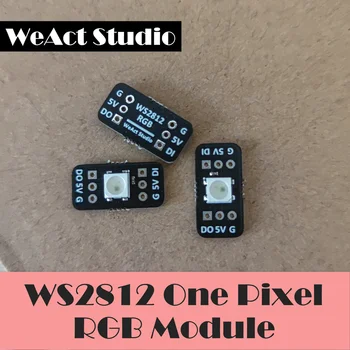
- RGB LED: WeAct Studio WS2812B breakout board x1
I used the single-chip breakout board type because it is easy to handle
Development Environment
- IDE: MounRiver Studio Ⅱ (the official VSCode-based development environment)
- SDK: official SDK (bundled with MRS2)
Wiring
Since the LED is driven by the microcontroller's built-in SPI peripheral, the control signal is output on the SPI MOSI pin (PC6).
Connections:
- Control signal input (DIN) → MOSI PC6 (pin 16)
- Power → 5 V supply (from the WCH-LinkE)
- GND → GND

Assembled on a mini breadboard, it looks like this. The RGB LED module is at the front right.

About the NeoPixel Control Signal
NeoPixel-type LEDs receive color data through their own timing-based signal. A data 0 or 1 is represented by the lengths of the High and Low periods.


Since a High pulse as short as 400 ns (2.5 MHz) has to be sent, the timing constraints are tight, and generating this signal from a microcontroller requires a special implementation.
There are broadly two ways to drive NeoPixel-type LEDs from a microcontroller.
- Direct GPIO control (bit-banging): adjust the timing with NOP instructions and toggle the GPIO on and off in software
- Any GPIO pin can be used
- Since the timing is on the order of 0.1 μs, delay functions are basically unusable, and fine timing adjustment by the number of NOP instructions is required (time for the oscilloscope or logic analyzer)
- Because it is done in software, the CPU is fully occupied while the signal is being sent. Interrupts cannot be used during that time because they would throw off the timing
- Using the microcontroller's built-in peripherals (a timer or SPI)
In the SPI case, you prepare special output data with the bits arranged so that the required signal is produced, and use DMA (Direct Memory Access) to transfer it sequentially to the peripheral's data register, which generates the signal.
- Signal generation is offloaded to the peripheral, so the CPU is not occupied
- Only the specific pins tied to the peripheral output can be used
- DMA is almost mandatory, which makes the implementation more complex. Without DMA, the software has to feed the data one piece at a time and the advantage fades.
This time I take the latter approach and generate the control signal with the CH32V003's SPI peripheral and DMA.
Fortunately, ch32fun, an open-source SDK for CH32V, has a WS2812B driver library, so I reuse it.
Preparing the NeoPixel LED Driver Library
Place ws2812b_dma_spi_led_driver.h from this link in your project's User folder. This library consists of a single header file, which you include from main.c or wherever you use it.
Some register definitions seem to differ between the official SDK and ch32fun, so the following parts of the code need to be changed.
Line 233
< 	GPIOC->CFGLR |= (GPIO_Speed_10MHz | GPIO_CNF_OUT_PP_AF)<<(4*6);
---
> 	GPIOC->CFGLR |= (GPIO_Speed_10MHz | GPIO_Mode_AF_PP)<<(4*6);
Line 244
< 	SPI1->CTLR1 |= CTLR1_SPE_Set;
---
> 	SPI1->CTLR1 |= SPI_CTLR1_SPE;
Program
I write a test program while referring to the following sample program.
ch32fun/examples/ws2812bdemo at master · cnlohr/ch32fun
Including the Library
Near the top of the file where you use the library (main.c if you call it from the main function), include the library header as follows.
#include "debug.h" // Write the lines below under this original include

#define WS2812DMA_IMPLEMENTATION
#define WSGRB // For WS2812B (order in which RGB data is sent)

#include "ws2812b_dma_spi_led_driver.h"
Callback Function for Setting the LED Color
Add the callback function WS2812BLEDCallback, which is called from the interrupt handler inside the library. This function receives the LED position ledno and must return a 24-bit value containing the color, 8 bits each in R, G, B order starting from the low bits.
To keep things simple, it just returns a single global variable ledVal for every LED. This global variable is updated from the main function written next.
static volatile uint32_t ledVal = 0; // Color value (global variable)

// Callback function for setting the color
uint32_t WS2812BLEDCallback(int ledno)
{
    return ledVal; // Return a 24-bit RGB value
}
Main Routine
Write the main routine in the main function. Initialize with WS2812BDMAInit, then call WS2812BDMAStart to light the LED in the color set in ledVal.
This assumes the debug feature is in use, so remove the printf lines if you do not need them.
int main(void)
{
    NVIC_PriorityGroupConfig(NVIC_PriorityGroup_1);
    SystemCoreClockUpdate();
    Delay_Init();
#if (SDI_PRINT == SDI_PR_OPEN)
    SDI_Printf_Enable();
#else
    USART_Printf_Init(115200);
#endif
    printf("SystemClk:%d\r\n",SystemCoreClock);
    printf( "ChipID:%08x\r\n", DBGMCU_GetCHIPID() );

    // Initialization function
    WS2812BDMAInit();

    // Lighting patterns
    static const uint32_t ledPatterns[] = {
        0x00000000, // Off
        0x000000FF, // Red
        0x0000FF00, // Green
        0x00FF0000, // Blue
        0x0000FFFF, // R + G = Yellow
        0x00FFFF00, // G + B = Cyan
        0x00FF00FF, // R + B = Magenta
    };

    // Show each color in turn
    for (unsigned int i = 0; i < sizeof(ledPatterns) / sizeof(ledPatterns[0]); i++) {
        // Assign the color value to the global variable
        ledVal = ledPatterns[i];

        // Debug output
        printf("LED val: %08X\r\n", ledVal);

        // Start the DMA transfer (1 = number of LEDs)
        WS2812BDMAStart(1);

        // Wait
        Delay_Ms(500);
    }
}
Checking the Result
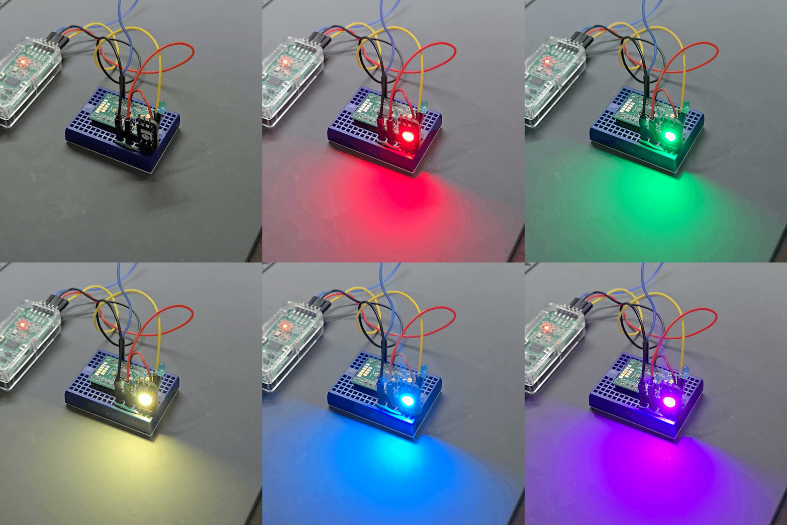
This is what it looks like when the program runs. (Everything is set to 0xFF for maximum brightness, so it is quite bright.)
As the program runs, you can see the LED light up in the order red → green → blue → yellow → cyan → magenta.
Summary
I was able to drive a WS2812B LED with the CH32V003 microcontroller. Only one LED is connected this time, but this library can also drive multiple LEDs, such as an LED strip.
I have not yet decided what to build with this microcontroller, but next I would like to try I2C.
References
- ch32fun WS2812B driver library (SPI + DMA version): https://github.com/cnlohr/ch32fun/blob/master/extralibs/ws2812b_dma_spi_led_driver.h
- Sample project using the library above: https://github.com/cnlohr/ch32fun/tree/master/examples/ws2812bdemo
- ch32fun WS2812B driver library (GPIO version): https://github.com/cnlohr/ch32fun/blob/master/extralibs/ws2812b_simple.h
- WS2812B datasheet (from Adafruit's site). Note that there are different revisions, and newer modules have different signal timing and other details: https://cdn-shop.adafruit.com/datasheets/WS2812B.pdf