Overview
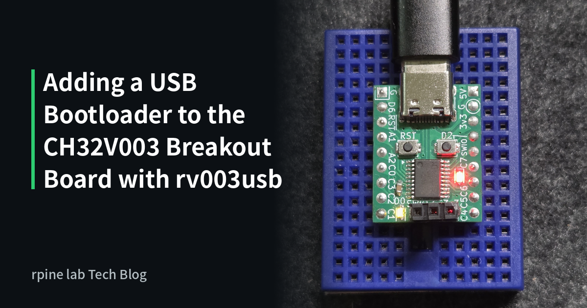
In the previous article (Building a General-Purpose CH32V003 Breakout Board in KiCad), I made a general-purpose breakout board for the CH32V003 microcontroller. This time I write the rv003usb USB bootloader to that board. With it, programs can be written directly with just a USB cable, without using the WCH-Link.
This article covers the USB circuit, configuring and writing the bootloader, changing the option bytes, and the code for entering the bootloader with the reset button.
rv003usb and the bootloader
The CH32V003 has no built-in USB peripheral, but rv003usb, a software USB implementation, makes USB available on it (higher-end parts such as the CH32V103 and CH32V203 have a USB peripheral).
This time I use the USB bootloader built on rv003usb so that programs can be written over USB.
USB circuit
I build the USB circuit as described in the rv003usb README.


Pin assignment
There are restrictions on which pins D+ and D− can be assigned to.
These two pins must be chosen from pins 0–4 of PORTA, PORTC or PORTD (that is, P[A,C,D]0–4). Both pins must also be on the same port (PORTA, for example).
On this board, the assignment follows the README (D+: PD3, D−: PD4).
D− pull-up (DPU) control
To control the USB connection state, a 1.5 kΩ resistor is connected to the D− pin, and its other end goes to PD5. If the device can always stay recognized, you can omit the DPU pin by pulling up directly to VCC (+3.3 V).
CC resistors
To get 5 V power from the host, the CC1 and CC2 pins are pulled down to GND through 5.1 kΩ resistors.
Damping resistors
33 Ω resistors are placed close to the microcontroller to reduce noise and for protection.
Preparing the bootloader
Development environment
- OS: Windows 11
- IDE (for building the bootloader): VSCode + PlatformIO extension
- IDE (for building user programs): MounRiver Studio Ⅱ
Cloning the rv003usb project
rv003usb includes ch32fun as a submodule, so clone it with --recursive.
git clone --recursive https://github.com/cnlohr/rv003usb.gitReplacing the WCH-Link driver
For writing and setting the option bytes, I use minichlink (ch32fun\minichlink\minichlink.exe), which comes with ch32fun.
To use the WCH-Link from minichlink, you need to replace the WCH-Link driver with WinUSB using Zadig.
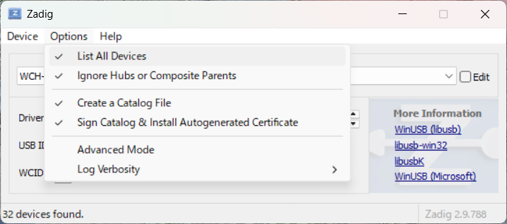
- Launch Zadig and turn on "Options" → "List All Devices"
- Select "WCH-Link (Interface 0)" from the list (of Interface 0 and 1, the one whose original driver is WCHLink_A64, not winser)
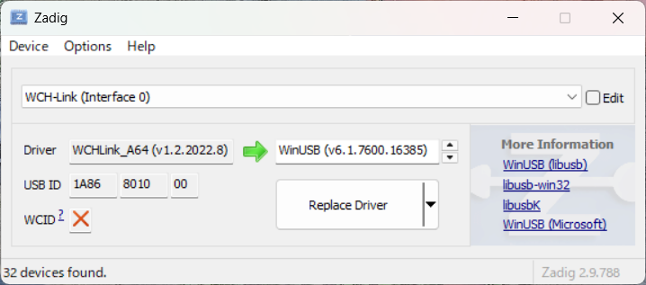
- Select "WinUSB" and click "Replace Driver"


You can revert it by updating the driver in Device Manager.
Bootloader settings
With the default settings, the bootloader runs for about 5 seconds after power-on and then starts the user program. This time, I change the #defines in bootloader/bootloader.c as follows so that it enters the bootloader only when the board is powered on while the user button (PD2) is held down.
#define DISABLE_BOOTLOAD

#define BOOTLOADER_BTN_PORT D
#define BOOTLOADER_BTN_PIN 2
#define BOOTLOADER_BTN_TRIG_LEVEL 0 // 1 = HIGH; 0 = LOW
//#define BOOTLOADER_BTN_PULL 1 // 1 = Pull-Up; 0 = Pull-Down; Optional, comment out for floating input

#define BOOTLOADER_TIMEOUT_PWR 0

//#define BOOTLOADER_TIMEOUT_USB 0
The button on this board goes low when pressed and has an external pull-up resistor, so the internal pull-up is not used. The timeout and USB host detection are disabled.
The USB pin settings (bootloader/usb_config.h) already match this board by default, so I leave them unchanged.
Building and writing with the WCH-Link
Open the rv003usb folder in VSCode, select env:bootloader in PlatformIO's environment switcher (toolbar), and build. Then write the resulting .pio\build\bootloader\firmware.bin to the bootloader area with the WCH-Link.
ch32fun\minichlink\minichlink.exe -w .pio\build\bootloader\firmware.bin bootloader -BOption byte settings
To boot from the bootloader at power-on, the option bytes also need to be written. Here, take care with the reset pin (NRST, PD7).
The value in the active (uncommented) command in rv003usb's bootloader/Makefile (+a55aff00) disables NRST. This board has a reset button on PD7, so the correct value to write is +a55aef10 (NRST enabled, boot from the bootloader at power-on).
ch32fun\minichlink\minichlink.exe -w +a55aef10 optionWriting programs over USB
Entering the bootloader
Connect the USB cable to power on the board while holding down the user button (PD2). The PC recognizes it as a HID device (VID:0x1209, PID:0xb003).

Creating the program to write
The bootloader is written to a dedicated area completely separate from the flash area where normal programs are written. So the user program needs no special linker script changes (such as offsetting the start address).
Code for entering the bootloader with the reset button
The option byte settings are used only at power-on, so pressing and releasing the reset button while holding the user button does not, by itself, enter the bootloader.
Which one starts at the next system reset is determined by the FLASH_STATR_MODE bit in FLASH->STATR (1: bootloader). However, when I actually tried it, the user program started right after a reset from the reset button (NRST) even though FLASH_STATR_MODE was 1 (FLASH_STATR_MODE is not cleared by an NRST reset).
So I add the following code at the beginning of the user program's main function. SystemReset_StartMode is a function in WCH's standard library (ch32v00x_flash.c).
int main (void) {
    if (FLASH->STATR & FLASH_STATR_MODE) {
        NVIC_SystemReset();
    }
    SystemReset_StartMode(Start_Mode_BOOT);

    // Normal processing follows
}- At power-on, the bootloader starts according to the option byte settings
- The bootloader sets
FLASH_STATR_MODEto 0 and starts the user program, so the first if statement is skipped SystemReset_StartModesetsFLASH_STATR_MODEto 1- On a restart with the reset button, the user program runs, but because
FLASH_STATR_MODEis 1,NVIC_SystemReset()in the if statement performs a software reset and the bootloader starts - If the user button is pressed, the bootloader stays as it is; if not, it starts the user program
Writing
With the board in the bootloader, write the file built in MounRiver Studio Ⅱ (the .bin in the obj folder) over USB.
.\ch32fun\minichlink\minichlink.exe -C b003boot -w [project folder]\obj\ch32v003-bo-brd.bin flash -b-C b003boot specifies that rv003usb's bootloader is used for writing. If it is omitted and a WCH-Link is connected, the WCH-Link takes priority.
Testing
I wrote the program used in the previous article (Building a General-Purpose CH32V003 Breakout Board in KiCad) (partly modified) over USB, and the LED blink program ran.
static uint8_t cnt = 0;

void UserPins_Init (void) {
    GPIO_InitTypeDef GPIO_InitStructure = {0};

    RCC_APB2PeriphClockCmd (RCC_APB2Periph_GPIOD, ENABLE);

    GPIO_InitStructure.GPIO_Pin = GPIO_Pin_0;
    GPIO_InitStructure.GPIO_Speed = GPIO_Speed_50MHz;
    GPIO_InitStructure.GPIO_Mode = GPIO_Mode_Out_PP;
    GPIO_Init (GPIOD, &GPIO_InitStructure);  // UserLED
}

int main (void) {
    if (FLASH->STATR & FLASH_STATR_MODE) {
        NVIC_SystemReset();
    }
    SystemReset_StartMode(Start_Mode_BOOT);

    NVIC_PriorityGroupConfig(NVIC_PriorityGroup_1);
    SystemCoreClockUpdate();
    Delay_Init();

    UserPins_Init();

    while (1) {
        if (cnt & 0x1) {
            GPIO_SetBits (GPIOD, GPIO_Pin_0);
        } else {
            GPIO_ResetBits (GPIOD, GPIO_Pin_0);
        }

        cnt++;
        Delay_Ms(200);
    }
}
Summary
I wrote the USB bootloader to the CH32V003 and made it possible to write programs over USB. Once the bootloader and option bytes have been written with the WCH-Link, programs can be rewritten with just a USB cable.